A floating ball can move with differential pressure and load the downstream seat. A trunnion-mounted ball stays supported while its seats move or energise towards the ball. These different load paths change which seat seals, how leakage appears, and how maintenance evidence should be read.
Design · Seat mechanics
Why trunnion and floating ball valve seats leak differently
Ball support and seat movement change loading, evidence and maintenance choices.
How a floating ball loads its seats
A floating ball is not rigidly supported by trunnions. Differential pressure can move the ball slightly towards the downstream seat. That movement increases contact load on that seat.
Seat behaviour therefore depends on pressure direction and differential pressure. A result at one pressure condition may not describe another condition. Low differential pressure may produce different contact from normal service.
Damage, debris, seal condition and incomplete travel can still cause leakage. Ball movement explains the loading path, but does not identify the defect. The differential pressure guide explains why test conditions matter.
How a trunnion valve loads its seats
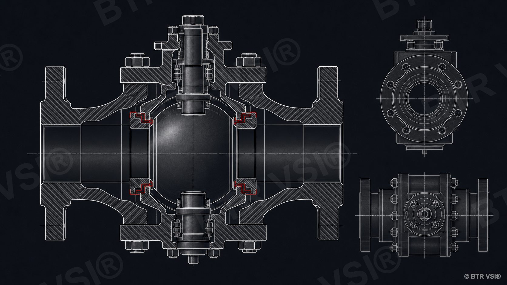
A trunnion-mounted ball is supported at its axis and has limited lateral movement. The seat assemblies provide the movement needed for contact. Springs, pressure action and seal geometry can all contribute, depending on the design.
Upstream and downstream seat behaviour may differ. Some designs can relieve body-cavity pressure in a defined direction. Others provide different isolation arrangements. Do not infer DBB or DIB performance from the word trunnion alone.
Use the valve drawing and OEM description to identify seat direction and cavity behaviour. Our cavity pressure guide covers why trapped pressure and relief behaviour can confuse field observations.
Why the leak pattern can differ
In a floating valve, leakage may change as pressure direction changes the ball load. In a trunnion valve, one seat may respond differently because its assembly, seals or pressure action differs from the other seat.
A cavity bleed observation can indicate leakage into the body cavity. It may not identify the passing seat without controlled steps and design knowledge. Temperature change, trapped product and a leaking bleed valve can add false signs.
Acoustic noise and downstream pressure rise remain screening evidence. Confirm seat integrity with a defined test arrangement. The field seat-leak testing guide compares pressure decay, DBB bleed and acoustic screening.
Maintenance implications are valve-specific
Start by confirming the exact design, flow direction, seat arrangement and injection system. Do not assume one injection point feeds both seats. Do not assume material seen at one port reached the damaged sealing face.
Before injection, the fittings must be in good condition. The valve design and service must suit injection, OEM guidance applies, and operations must permit the work. Use controlled amounts within equipment and fitting ratings while watching pressure response.
For floating valves, test direction and differential pressure deserve close attention. For trunnion valves, cavity behaviour and individual seat paths often need separate records. In both designs, a successful temporary seal does not prove the underlying damage is minor.
See the sealant injection guide for the general method and product selection by valve design for compatibility logic. Field valve services can assess the exact seat and injection arrangement.
A design sketch often resolves early confusion. Mark pressure direction, ball support, both seats and cavity ports. Then place each test observation on that sketch. This keeps the diagnosis tied to the actual flow path.
Common questions
Trunnion versus floating questions
What is the main seat-loading difference between floating and trunnion ball valves?
A floating ball can move towards the downstream seat under differential pressure. A trunnion ball stays supported, so its seat assemblies move or energise towards the ball.
Does every trunnion ball valve provide the same DBB or DIB behaviour?
No. Seat direction, pressure action and cavity relief depend on the exact design. Confirm them from the valve drawing and OEM information.
Can a cavity bleed test identify the leaking seat?
Not always. Controlled steps and design knowledge are needed. Trapped pressure, temperature change, relief behaviour or a leaking bleed valve can confuse the result.
Are sealant injection paths the same in both designs?
No. Injection arrangements are valve-specific. Confirm which port serves each seat and whether the design, service, fittings and operating plan permit injection.
Seat behaviour is unclear?
Send the valve drawing. An engineer replies within 24 hours.
Include pressure direction, seat arrangement, test conditions and observed leakage pattern.